

Design and Construction of Flexible Pavement
Pavement forms a major chunk of the Public Works department and optimum & sound design is key to save on future recurring maintenance, the Contracts from NHAI, MoRTH, State PWD’s which are on EPC, HAM, PPP mode call for contractors own design. Most projects entail combination work of new crust (widening) and rehabilitation/ reconstruction of existing pavement. Very important to asses the existing pavement, site conditions, material availability, traffic etc. for finalization of pavement crust. For department point of view it is important to asses whether the desig submitted by DPR consultant, EPC contractor is as per the site conditions and codal provisions.
Important IRC Guidelines for Design and construction of flexible pavement
New pavement design
IRC:37-2018 --> Guidelines for the Design of Flexible Pavements --> Applicable to new road, widening portions, reconstruction of damaged pavements
Overlay Design of existing flexible pavement
IRC:081-2014 --> Guidelines for Strengthening of Flexible Road Pavements Using Benkelman Beam Deflection Technique (BBD)
IRC:115-2014--> Guidelines for Structural Evaluation and Strengthening of Flexible Road Pavements using Falling Weight Deflectometer (FWD)
FLEXIBLE PAVEMENT BASICS


Stress distribution with depth
COMPONENTS OF FLEXIBLE PAVEMENT

| Density Requirement of embankment and subgrade materials | ||
| SR. No. | Type of work | Max Dry Density as per IS:2720 Part 8 |
| 1 | Embankment upto 3 m. | Not less than 15.2 KN/M3 |
| Not subject to extensive flood | 1.52 T/m3 | |
| 2 | Embankment upto 3 m.height | Not less than 16 KN/M3 |
| subject to Long Inundation. | 1.52 T/m3 | |
| 3 | Sub grade and earthen shoulders/verges/backfill | Not less than 17.5 KN/M3 |

Soil Subgrade

Grading
for granular sub base material (
as per MORTH page 109)
| IS sieve in mm | % by weight passing the IS Sieve | |||||
| Grading 1 | Grading 2 | Grading 3 | Grading 4 | Grading 5 | Grading 6 | |
| 75 | 100 | - | - | - | 100 | 100 |
| 53 | 80-100 | 100 | 100 | 100 | 80-100 | 80-100 |
| 26.5 | 55-90 | 70-100 | 55-75 | 50-80 | 55-90 | 55-90 |
| 9.5 | 35-65 | 50-80 | - | - | 35-65 | 35-65 |
| 4.75 | 25-55 | 40-65 | 10 - 30 | 15-35 | 25-90 | 25-90 |
| 2.36 | 20-40 | 30-50 | - | - | 10-20 | 10-20 |
| 0.85 | - | - | - | - | 2-10 | 2-10 |
| 0.425 | 10 - 15 | 10 - 15 | - | - | 0-5 | 0-5 |
| 0.075 | <5 td=""> | <5 td=""> | <5 td=""> | <5 td=""> | - | - |
| Physical requirement for material for GSB | ||
| Aggregate impact value (AIV) | IS 2386 part 4 or IS 5640 | 40 % max |
| Liquid limit | IS 2720 part 5 | 25 % max |
| Plasticity Index | IS 2720 part 5 | 6 % max |
| CBR at 98 % dry density (at IS 2720 part 8) | IS 2720 part 5 | min 30 unless specified in contract |

| Physical Requirement of Cource Aggregates for WBM for Sub-base/base course | |||
| Type of test | Test Method | Base On Course | When WBM used for sub-base courses |
| Loss angeles abrasion value | IS 2386 part 4 | 40% max | 0.5 |
| Aggregate Impact value | IS 2386 part 4 | 30% max | 0.4 |
| Combined Flakiness and elongation Indices | IS 2386 part 1 | 35% max | |
| Grading Requirement of course aggregates for WBM for subbase/base course | |||
| Size Range | IS Sieve size | % by wt.passing | |
| Grading 1 | 63 mm to 45 mm | 75 mm | 100 |
| 63 mm | 90-100 | ||
| 53 mm | 25-75 | ||
| 45 mm | 0-15 | ||
| 22.4 mm | 0-5 | ||
| Grading 2 | 53 mm to 22.4 mm | 63 mm | 100 |
| 53 mm | 95-100 | ||
| 45 mm | 65-90 | ||
| 22.4 mm | 0-10 | ||
| 11.2 mm | 0-5 | ||
| Size Of Screening | IS Sieve size | % by wt. passing | |
| A | 13.2 | 13.2 mm | 100 |
| 11.2 mm | 90-100 | ||
| 5.6 mm | 25-75 | ||
| 180 micron | 0-15 | ||
| B | 11.2 | 11.2 mm | 100 |
| 9.5 mm | 95-100 | ||
| 5.6 mm | 65-90 | ||
| 180 micron | 0-10 |
| Grading Requirements of Aggregate for wet mix macadam For base courses | |
| 53.00 mm | 100 |
| 45.00 mm | 95-100 |
| 26.50 mm | - |
| 22.40 mm | 60-80 |
| 11.20 mm | 40-60 |
| 4.75 mm | 25-40 |
| 2.26 mm | 15-30 |
| 600 micron | 8-22 |
| 75 micron | 0-5 |
| Material finer than 425 micron shall have plasticity index (PI) not exceeding 6 | |

Consumption For Binder & Surface course Layers used in Maharashtra PWD.
| BBM 75 mm | |||
| Materials | Unit | 100 | Sqm |
| Component | Quantity | Unit | |
| Bitumen VG 30 (Bulk) (60/70) | 0.2 | M.T. | |
| Aggregates 12 mm | 1.8 | Cu.Mt. | |
| Trap metal 40 mm blasted | 9 | Cu.Mt. | |
| BBM 50 mm | |||
| Materials | Unit | 100 | Sqm |
| Component | Quantity | Unit | |
| Bitumen VG 30 (Bulk) (60/70) | 0.175 | M.T. | |
| Aggregates 12 mm | 1.8 | Cu.Mt. | |
| Trap metal 40 mm blasted | 6 | Cu.Mt. | |
| BUSG | |||
| Materials | Unit | 100 | Sqm |
| Component | Quantity | Unit | |
| Bitumen VG 30 (Bulk) (60/70) | 0.3 | M.T. | |
| Aggregates 22.4 to 2.36 mm | 1.3 | Cu.Mt. | |
| Aggregates 53 to 2.8 mm | 10 | Cu.Mt. | |
| BM 3.3% | |||
| Materials | Unit | 100 | Cu.m |
| Component | Quantity | Unit | |
| Bitumen VG 30 (Bulk) (60/70) | 7.24 | M.T. | 0.033 |
| Aggregates 37.5 to 25 mm | 22.21 | Cu.Mt. | |
| Aggregates 25 to 10 mm | 53.9 | Cu.Mt. | |
| Aggregates 10 to 5.5 mm | 35.38 | Cu.Mt. | |
| Aggregates below 5.6 mm | 22.21 | Cu.Mt. | |
| BM 3.4% | |||
| Materials | Unit | 100 | Cu.m |
| Component | Quantity | Unit | |
| Bitumen VG 30 (Bulk) (60/70) | 7.989 | M.T. | 0.034 |
| Aggregates 37.5 to 25 mm | 22.21 | Cu.Mt. | |
| Aggregates 25 to 10 mm | 53.9 | Cu.Mt. | |
| Aggregates 10 to 5.5 mm | 35.38 | Cu.Mt. | |
| Aggregates below 5.6 mm | 22.21 | Cu.Mt. | |
| DBM 4.5% | |||
| Materials | Unit | 100 | Cu.m |
| Component | Quantity | Unit | |
| Bitumen VG 30 (Bulk) (60/70) | 11.16 | M.T. | 0.045 |
| Aggregates 37.5 to 25 mm | 32.4 | Cu.Mt. | |
| Aggregates 25 to 10 mm | 19.15 | Cu.Mt. | |
| Aggregates 10 to 5.6 mm | 27.989 | Cu.Mt. | |
| Aggregates below 5.6 mm | 61.82 | Cu.Mt. | |
| LDO | |||
| Stone dust | 4.42 | Cu.Mt. | |
| BC 5.5% | |||
| Materials | Unit | 100 | Cu.m |
| Component | Quantity | Unit | |
| Bitumen VG 30 (Bulk) (60/70) | 13.92 | M.T. | 0.055 |
| Aggregates 13.2 to 10 mm | 44.76 | Cu.Mt. | |
| Aggregates 10 to 5.6 mm | 37.303 | Cu.Mt. | |
| Aggregates below 5.6 mm | 64.16 | Cu.Mt. | |
| LDO | 1500 | Ltr. | |
| Stone dust | |||
| Open graded Premix Surfacing 20 mm thick | |||
| Materials | Unit | 100 | Sq,m |
| Component | Quantity | Unit | |
| Bitumen VG 30 (Bulk) (60/70) | 0.244 | M.T. | 20 mm thick |
| Aggregates 13.2 to 5.6 mm | 2.7 | Cu.Mt. | |
| Aggregates below 5.6 mm | 0.9 | Cu.Mt. | |
| LDO | 24 | Ltr. | |
| Closed graded Premix Surfacing 20 mm thick | |||
| Materials | Unit | 100 | Sq,m |
| Component | Quantity | Unit | |
| Bitumen VG 30 (Bulk) (60/70) | 0.19 | M.T. | 20 mm thick |
| Aggregates 13.2 to 0.09 mm | 2.7 | Cu.Mt. | |
| LDO | 24 | Ltr. | |
FLEXIBLE PAVEMENT DESIGN CONCEPT
STRUCTURAL DESIGN & MIX DESIGN
PAVEMENT DESIGN PARAMETERSNEW CRUST (IRC 37-2018)
Subgrade strength
• California Bearing Ratio CBR (%) :-
Step 1) Soil Sampling is done, CBR value for each sample is calculated, then 90 percentile CBR value is taken as CBR value of Subgrade of Existing Pavement location.
Step 2) CBR value of Borrow pit material is Calculated
Step 3) Effective CBR from 90 percentile CBR value of existing pavement and CBR value of borrow pit material is obtained from graph of Fig 5.1 of IRC:37

Lab Testing CBR

Field CBR Testing
• Existing Soil subgrade / Borrow area soil
• Subgrade Resilient Modulus (Mpa)
Subgrade Soil
Top 500 mm of soil is known as Subgrade
Strength measured in terms of % CBR & modulus
Samples collected at every 500 to 1000 m or where soil strata changes to give proper representation
Soil sample collected at depth of average 1 to 1.25 m (from existing BT) for widening portions
Subgrade material should have dry density not less than 1.75 g/cc

| Compaction Requirement of embankment and subgrade | ||
| SR. No. | Type of work | Relative compaction as % of Max laboratory Dry Density as per IS:2720 Part 8 |
| 1 | Embankment Not subject to extensive flood | Not less than 95% |
| 2 | Sub grade and earthen shoulders/verges/backfill | Not less than 97% |
Traffic
• Average Daily Traffic (CVPD)
• Million Standard Axles (MSA)
Material Strength/ properties
• Resilient Modulus of GSB, WMM, DBM, BC, CTB etc
• Poisson ratio
LABORATORY & FIELD CBR TEST (IS: 2720) AND OTHER SOIL TESTS
CBR (California Bearing Ratio) is a penetration test for evaluating the strength of Soil Subgrade
CBR represents the % of load taken by a Soil sample as compared to a Standard sample of crushed stones
4 Day soaked CBR test is conducted to simulate worst condition for subgrade soil in field
Minimum CBR for design 8 %
Soil classification, liquid limit, Plastic limit, PI values, FSI etc to assess suitability for use
Traffic Factors
Initial Traffic – Commercial Vehicles Per Day (CVPD)
Commercial vehicle – gross weight > 3000 Kg
Collected by conducting 7 days 24 Hour Classified Traffic Volume Count
Traffic Growth Rate
Based on last Traffic counts (past trends)
If adequate data not available then 5.00 %
Design Life (Years)
20 years for NH, SH and Urban Roads
Highways with very high intensity >300MSA- 30 years
20 years for Expressways
15 years for Other Category Roads
Vehicle Damage Factor
Vehicle Damage Factor (VDF) - multiplier for converting number of commercial vehicles of different axle loads and configurations to number of standard axle-load repetitions.

Every passage of a vehicle cause a certain amount of damage
Degree of damage depends on gross weight, number of axles and configuration of wheels.
e.g 13 Ton on single axle causes almost 12 times more damage than 13 Ton tandem axle
Gross load is transferred to pavement surface over a wider area by more number of axles and wheels
COMPUTATION OF VDF
$$VDF = {\text{ Total damaging effect}\over \text{Number of vehicles weighed}}$$
$$\text{Total damaging effect} ={\left(\text{Actual Weight of axle}\over \text{Standard weight of Axle}\right)}^4$$
General Load data

Front Axle = 6600 kg
Rear Axle = 8160 kg
Tandem Axle = 14968 kg
Tridem Axle = 22400 kg
If no Actual load survey is done then for design VDF can be taken from following table
| Initial traffic | Rolling Terrain | Hilly Terrain |
| 0 - 150 CVPD | 1.7 | 0.6 |
| 150 -1500 | 3.9 | 1.7 |
| > 1500 | 5 | 2.8 |
Lane Distribution Factor
Single Lane – 1.00 (both sides)
Two lane – 0.75 (both sides)
Four Lane Single Carriageway – 0.4 (both sides)
Dual Carriageway
Two lane dual carriageway - 0.75 of traffic in each direction
Three lane dual carriageway 0.60 of traffic in each direction
Four lane dual carriageway 0.45 of traffic in each direction
Design Traffic - MSA
$${N_c} ={{365\times A[{(1+r)^n}-1]}\over r}\times F \times D$$
where,
Nc = Cumulative Standard Axles to be catered for in the design in Million Standard Axles
A = Initial traffic, after completion of construction, in terms of commercial vehicles per day (CVPD)
r = Annual growth rate of commercial traffic.
n = Design life in years
F = VDF (number of standard axles per Commercial axle)
D = Lane Distribution Factor
Standard design catalogues in IRC 37 2018
Design catalogues are provided for ready reference in IRC 37 2018 one example as shown below

Various combination of pavement layers for CBR from 5 to 15 % and traffic upto 50 MSA are given.
Using catalogues one can design flexible pavements, one example is demonstrated in video
Separate charts for conventional pavement crust, CTB, CTSB layers, Foam bitumen stabilized RAP material, SAMI
For pavements with CTB separate fatigue analysis is also required using the Axle Load spectrum data
MECHANISTIC -EMPIRICAL DESIGN (NEW CONCEPT FROM IRC 37-2012)
• Pavement design involves designing pavement for satisfactory Functional and Structural performance of the pavement during intended service life period.
• Roughness caused by variation in surface profile, Cracking of layers -bituminous or cementitious materials, Rutting (permanent or plastic deformation) of unbound/unmodified or partially modified subgrade, granular layers and bituminous layers are primary indicators of the functional and structural performance of pavements.
FLEXIBLE PAVEMENT FAILURE CRITERIA
1) Fatigue Cracking Area above 20 %

2) Rutting above 20 mm

MECHANISTIC EMPIRICAL DESIGN
Performance is explained by performance models either (a) purely empirical (only based on past experience) or (b) mechanistic-empirical, in which the distresses/performance are explained in terms of mechanistic parameters such as stresses, strains and deflections
Most of the current pavement design methods follow Mechanistic Empirical approach for the design of bituminous pavements.
For each of the selected structural distresses, critical mechanistic parameter is identified and controlled to an acceptable (limiting) value in the design process.
The limiting values of these critical mechanistic parameters are obtained from the performance models.

Vertical compressive strain on top of the subgrade is considered to be the critical mechanistic parameter for controlling subgrade rutting.
Horizontal tensile strain at the bottom of the bottom bituminous layer is taken as the mechanistic parameter which has to be limited to control bottom-up cracking in bituminous layers.
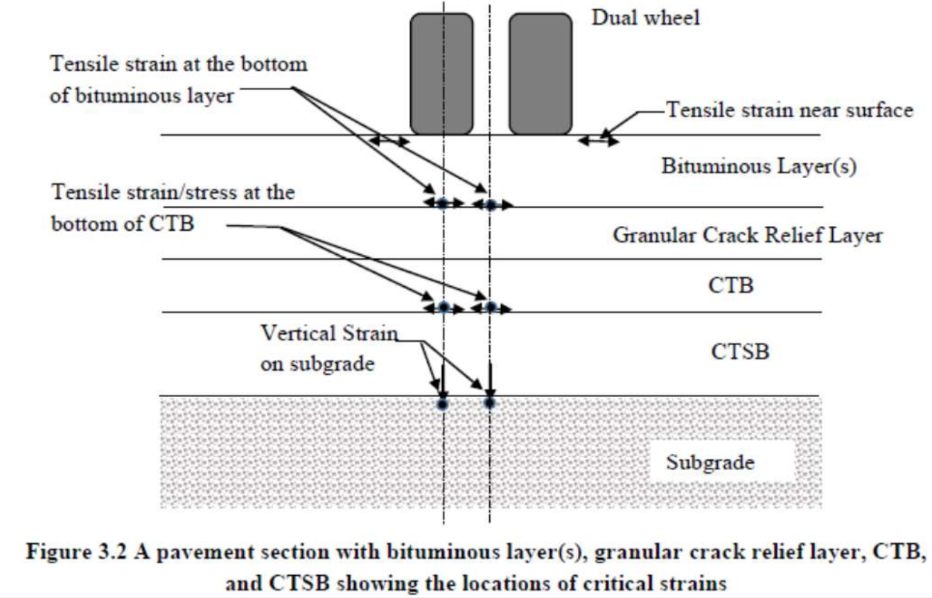
Similarly, to ensure that the Cement Treated Bases (CTB) do not fail by fatigue cracking, tensile strain and tensile stress at the bottom of the CTB are considered to be the critical parameters to control.
RELIABILITY CONCEPT
• Design reliability probability that pavement section will perform satisfactorily over the design period.
• IRC Guidelines recommend 90% reliability performance equations for subgrade rutting and fatigue cracking of bottom bituminous layer for all important roads such as Expressways, NH, SH and Urban Roads
• For other categories of roads, 90 % reliability is recommended for design traffic of 20 msa or more and 80 % reliability for design traffic less than 20 msa.
For 80% reliability
$${N_R}= 4.1656 \times {10^{-08}}\times{{\left[1\over \epsilon_v \right]}^{4.5337}}$$
For 90% reliability
$${N_R}= 1.41 \times {10^{-08}}\times{{\left[1\over \epsilon_v \right]}^{4.5337}}$$
Where,
NR = Subgrade Rutting life (cumulative equivalent number of 80 KN Standard axle loads that can be served by the pavement before the critical rut depth of 20 mm or more occurs)
εv = Vertical compressive strain at the top of the subgrade calculated using Linear elastic layered theory by applying standard axle load at the surface of selected pavement system.
SUBGRADE RUTTING CRITERIA
An average rut depth of 20 mm or more, measured along the wheel paths, is considered as critical or failure rutting condition.
For 80% reliability
$${N_f}= 1.6064 \times {10^{-04}}\times{{\left[1\over \epsilon_t \right]}^{3.89}}\times{{\left[1\over M_{Rm} \right]}^{0.854}}$$
For 90% reliability
$${N_f}= 0.5161 \times {10^{-04}}\times{{\left[1\over \epsilon_t \right]}^{3.89}}\times{{\left[1\over M_{Rm} \right]}^{0.854}}$$
FATIGUE CRACKING CRITERIA FOR BITUMINOUS LAYER
Fatigue cracking (appearing as inter connected cracks), whose total area in section of road under consideration is 20 % or more than paved surface area, is considered critical or failure condition.
IIT PAVE SOFTWARE FOR STRESS STRAIN ANALYSIS
To Calculate stress and strains at top and bottom of various layers IIT pave software can be used.

Inputs in IIT pave are as shown below

1) SUBGRADE RESILIENT MODULUS
For CBR ≤ 5%
$${M_{RS}}=10\times CBR$$
For CBR > 5%
$${M_{RS}}=17.6\times (CBR)^{0.64}$$
2) Load
3) Tyre Pressure
4) Depth
5) Poisson Ratio
6) Thickness
7) Radius
Output of IIT pave software is as shown below

Recommended Material properties for structural layers
| Material Type | Elastic\Resilient Modulus (MPa) | Poisson's ratio |
| Bituminous layer with VG40 or modified bitumen | 3000 or tested value whichever is less | 0.35 |
| Bituminous layer with VG30 | 2000 or tested value whichever is less | 0.35 |
| Cement treated base | 5000 | 0.25 |
| Cold recycled base | 800 | 0.35 |
| Granular Interlayer | 450 | 0.35 |
| Cement treated Sub-base | 600 | 0.25 |
| Unbound Granular layers | Use eq. 7.1 of IRC 37 | 0.35 |
| Unbound granular base over CTSB Sub-base | 300 for Natural gravel | 0.35 |
| 350 for Crushed aggregates | ||
| Subgrade | Eq. 6.1 or 6.2 of IRC 37 | 0.35 |
PROPERTIES OF ROAD MATERIALS AS PER IRC 37-2018
E value of BC = 1700-3000 MPa
E value of DBM = 1700-3000 MPa
E value of WMM = 350-450 MPa
E value of GSB = 160 MPa
E value of Subgrade = 60-70 MPa
E value of Stabilized Layer = 5000-8200 MPa
Indicative values of resilient modulus (MPa) of bituminous mixes
| Mix Type | Average Annual Pavement Temperature (oC) | ||||
| 20 | 25 | 30 | 35 | 40 | |
| BC and DBM for VG 10 Bitumen | 2300 | 2000 | 1450 | 1000 | 800 |
| BC and DBM for VG 30 Bitumen | 3500 | 3000 | 2500 | 2000 | 1250 |
| BC and DBM for VG 40 Bitumen | 6000 | 5000 | 4000 | 3000 | 2000 |
| BC with modified Bitumen (IRC:SP:53) | 5700 | 3800 | 2400 | 1600 | 1300 |
| BM with VG10 Bitumen | 500 MPa at 35oC | ||||
| BM with VG10 Bitumen | 700 MPa at 35oC | ||||
| RAP treated with 4% Bitumen emulsion/ foamed bitumen with 2 -2.5% residual bitumen and 1% cementitious material | 800 MPa at 35oC | ||||
RECOMMENDATION FOR LAYER SELECTION
For high traffic volume roads with a design traffic of 50 msa or more,
(a) Stone Matrix Asphalt (SMA)
(b) Gap Graded mix with rubberized bitumen (GGRB),
(c) Bituminous Concrete (BC) with modified binders, are recommended for surfacing course
SMA mix recommended for high traffic volume roads
Use of modified binders is preferred for longer service life and more resistant to aging
For traffic above 20 MSA, VG 40 is mandated for DBM, BC and other hotmix layers
For highly stressed areas or roads in high rainfall areas and junction , mastic asphalt mix can be used as an alternative surface course.
For Non-National Highway roads with less than 20 msa traffic, for surface course Bituminous Concrete, Semi Dense Bituminous Concrete (SDBC), Pre-Mix Carpet (PMC), Mix Seal Surfacing (MSS), Surface Dressing (SD) with unmodified binders.
Thin bituminous layers such as PC, MSS and SD shall not be considered as part of the bituminous layer for analysis of the pavement.
PROVISIONS FOR EXPANSIVE SOILS
BC Soils are common in India
Exhibit high expansion and contraction on variation in moisture and lead to distortion, cracking
Buffer Layer
Non expansive cohesive soil cushion 0.6 to 1.0 m thickness
Blanket Course
At least 225 mm thick coarse/ medium sand or non plastic murum of PI less than 5 as sub base on expansive soil
Alternatively Lime stabilized Black Cotton sub base over entire formation with along with efficient drainage measures
Soil Stabilization (cement/ lime/ chemical additives) also recommended
IRC PROVISIONS FOR STABILIZED BASE USE IN ROAD CONSTRUCTION
IRC 37 2012, 2018 gives design guidelines for use of Stabilized Base layers and the reduction in thickness of the BT layers
IRC SP 89 2018 have given the guidelines for material specifications and test methods for stabilized base layers
IRC has accredited number of manufacturers of stabilizer products for use on site
Already this type of stabilized base work is being done on many PWD Maharashtra and NH projects in India


0 Comments
If you have any doubts, suggestions , corrections etc. let me know