

Truss Analysis by Graphical method

Force is completely determined when it is known in amount, in direction, and in point of application, any force may be represented by a length, direction, and position of a straight line.
The length of the line is fixed by the relation between the amount of the given force and a pre-arranged unit of force. If the unit of force be taken as one Newton, line of 3 meter long represents a force of 3 Newton. The graphical representation of a force may be designated by marking the line representing. The force with the letter P followed in the same instances by a subscript.

Figure 1A
Extremity of the line may be indicated by a letter and the force referred to by means of these letters.

Figure 1B
The direction of the force may be given where necessary by an arrow on the line representing the force. In the second method of designation given above, the order of the letters given in referring to a force indicates its direction that is in figure 1B, referring to the upper force as ab Indicates that it acts from "a" towards "b" while reference to the lower force as "ca" Indicates that it acts from "c" towards "a".A diagram such as Figure 1.(a or b) Which showed the analytical relation of the forces acting their positions, directions and amounts is known as "forced diagram".
Composition and resolution of forces
In Figure 2, P1 and P2 represents 2 forces in the same plane acting at a point a. The amount of the resultant of the two forces is given by the length of the diagonal of the parallelogram "abcd" Constructed upon the two given forces as sides, a single force applied at a point a acting in the direction of point b of an amount represented by the length of the line ab will replace P1 and P2 in so far as accomplishing work is concerned. A force of the same amount but acting in the opposite direction will hold the forces P1 and P2 in equilibrium. That is at rest if the force represented by the line ab acts from a towards b. It is the resultant if it acts from b towards a. It is the anti-resultant of the given forces. If another force P3 were acting at a point a, it could be combined in a similar manner with the resultant of P1 and P2. To determine the resultant of P1, P2 and P3. The process of replacing forces P1 and P2 and more if present with the single force ab is called the composition of forces. Two or more forces are combined into one, on the other hand, any single force may be resolved into two components acting in any given directions. The solution of this problem, called the resolution of forces, is the reverse of that employed in the composition of forces.
The Force Triangle
Reference to figure 2 shows that; in order to determine the amount and the direction of the resultant of P1 and P2, it is not necessary to construct the complete parallelogram "abcd".From "c" of the force P1 and a line "cb" is drawn parallel and equal to P2.The triangle "acb" is called the "force triangle" and the represents graphically the relation between the forces P1, P2 and "ab". Thus, it is seen that in if in addition to forces P1 and P2, a third force "ba" is applied at point "a" in the direction from b to a, these three forces will be in equilibrium. The point a will then remain at rest. It may now be concluded that., If three forces meeting in a point are in equilibrium, they will form a closed triangle i.e. not only one in which the three lines parallel and equal to the three forces respectively form a closed three sided figure but one in which the arrows representing the direction of the forces all point in the same direction around the triangle.
By applying this principle, any one of three forces may be determined in amount and direction if the other two are fully known, or any two of these forces may be obtained in amount if their directions are given and the third force is fully known.
The force Polygon.


Force triangle for forces 1 and 2


Similar way solving further
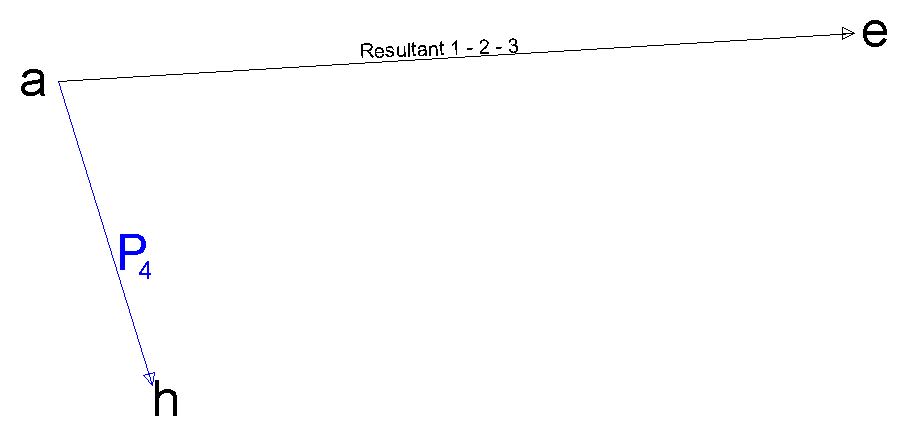
Resultant of Forces 1 - 2 - 3 with Force P4

Resultant of Forces 1 - 2 - 3 -4 obtained

Resultant with All forces

Shortcut method by force polygon
Application of the force Polygon

The Crane Trust of Figure 5 consists of a vertical post "bd" supporting a boom "dc", from which the external load P1 is suspended. The boom is anchored to the post by the tie rod "bc" and the post is in turn anchored at its upper end by the backstay ab fastened to the ground. In constructing the force Polygon, P1 (=mn) is laid off equal to the external load. By drawing mk and nk Parallel to T2 and T1 respectively, the values of the stresses in these two members are obtained. Similarly mj and kj determine the stresses in T3 and T4. In the triangle mnk, the direction of the P1 is known, following around the triangle in the direction indicated by P1, S1 acts from n to k; and transferring this direction to the trust diagram, the stress in T1 acts towards the joint c and is therefore compression. Proceeding in the direction from k to m, the stress in T2 is tension. In the triangle kmj, Since T2 is in tension and acts away from the Joint b, the direction to be taken around the triangle is from m to k.This indicates tension in T3 and compression in T4.
The equilibrium Polygon

The preceding paragraphs have dealt with the concurrent forces only. With concurrent forces the method so far used become cumbersome and with a system of parallel forces do not furnish a solution. A general method applicable to all cases involving coplanar forces is illustrated in Figure 6. The forces P1, P2, P3 and P4 acting upon the given body are not in equilibrium. The amount and direction of the resultant are obtained from the force Polygon "abcde". The line of action of this resultant may be determined as follows.
From any point "o"In the force Polygon, a line may be drawn to each of the vertices of the Polygon. Since the lines "oa" and "ob" form a closed triangle with the force P1, They represent 2 forces that will hold P1 in equilibrium i.e. 2 forces that may replace P1 in the force diagram. In Figure 6 at any point m on the line of action of P1 lines "mn" and "mv" drawn parallel to S1 and S5 respectively represents the line of action of these two forces. similarly S1 and S2 represents two forces that may replace P2.The line of action of S1 has already been fixed by the line "mn".From the point of intersection n of the line mn with the force P2, nr is drawn parallel to S2.From r, rs is drawn parallel to S3; and from s, st is drawn parallel to S4. Lines, nv and st, which are parallel to S5 and S4 respectively, represent the line of action of S5 and S4. These latter forces, together with the resultant ae form a closed force triagle.
S5, S4 and ae therefore represent a series of three forces in equilibrium. To fulfill these conditions where three forces only are involved, the three forces must meet at a point. The line of action of the resultant ae must therefore pass through the point of intersection w of the lines mo and st. The resultant of the for given forces is thus fully determined. A force of equal magnitude but acting in the opposite direction, that is, from e to a (in the direction of the forces in the force Polygon) will hold P1,P2,P3 and P4, in equilibrium and keep the body on which they act at rest.
The Polygon mnrsw represents a jointed frame which, by means of stresses of tension and compression in its various members, could hold the given forces in equilibrium. It is called therefore an equilibrium Polygon. The amount and the character of stress in each of the members of the jointed frame are given by the lines as S1.............S5 in the force Polygon. The point O is called the "pole" and the lines S1.............S5 are called the "rays" of the force Polygon. Obviously, since an infinite number of poles may be selected and an infinite number of starting points may be used, an infinite number of equilibrium polygons may be drawn for a group of forces. The final result will however be the same for all i.e. The line of action of the resultant of any given force group, determined by one equilibrium Polygon, will coincide with that found by any of the other possible polygons.
Resultant of parallel forces.
In the case of a system of parallel forces, the force Polygon becomes a straight-line figure represents 7 represents a system of four such forces not in equilibrium. The force Polygon abcde is a straight line and ae is closing line gives the magnitude and the direction of the resultant. For convenience in the following construction, the forces representing by each of the lines of the force Polygon. In the figure, seven are indicated at the right of the Polygon to hold the given forces in equilibrium of force equal in amount to ease a acting upwards from east to a is necessary. The line of action of these forces is determined from the equilibrium Polygon.
The pole o is selected and the rays drawn to the vertices of the force Polygon from any point on the line of action of P1, lines mt and drawn parallel to ob and oa. (the rays that form with P1 closed force triangle) respectively from n, the point of intersection of mn and the line of action of P2, A line nr is drawn parallel to oc. A from r, online rs is drawn parallel to od and from s, a line sv is drawn parallel to oe. the point of intersection w of the lines mt and sv is a point in the line of action of resultant force. An upward force equal and parallel to ea, applied so that its line of action passes through. Point will hold the forces P1........P4 in equilibrium. Downward force of the same amount will replace the given forces.

Solving Roof truss using above Methods


0 Comments
If you have any doubts, suggestions , corrections etc. let me know