

Design and Construction of Rigid Pavement

Due to frequent maintenance requirements of Flexible pavements Rigid pavement has become a preferred choice by Highway agencies.
If designed and CONSTRUCTED properly by exercising strict supervision and Quality checks the Rigid pavement does offer a service life of above 30 years with minimal maintenance.
Example of Mumbai Pune Expressway completed in year 1999- still 90-95 % of the stretch in good-excellent condition.
We have various options for designing of Rigid Pavements- Design and Construction Practice manuals are as follows-
Rigid Pavement :- Those Pavements which poses note worthy flexural strength or flexural rigidity. In rigid pavement the stresses are not transferred by aggregate interlock mechanism to the lower layers (as in case of flexible pavement). The rigid pavements are made of Portland cement concrete either plain or reinforced concrete. The plain cement concrete slabs are expected to take up about 4.5 MPa flexural stress. The rigid pavement has a slab action and is capable of transmitting the wheel load stresses through a wider area below. Tensile stresses are developed due to the bending of the slab under the wheel load temperature variations Providing a good base at sub base course layer under the cement concrete slab increase the pavement life considerably and there for workout more economical in the long run. The rigid pavements are usually designed and the stresses are analysed using the elastic theory.
1) IRC 58-2015 – Guidelines for Design of Plain Jointed Rigid Pavements for Highways / Rigid Pavements (JPCP),
2) IRC 101( CRCP)- Guidelines for Design of Continuously Reinforced Concrete Pavement with Elastic Joints
3) IRC SP 118- 2015 – Guidelines for Design and Construction of Continuously Reinforced Concrete Pavement (CRCP)
4) IRC SP 76 - 2014 (TWT) Guidelines for design of Thin White Topping pavements
5) IRC 15-2017- Standard Specifications and Code of Practice for Concrete Roads
6) IRC SP-62-2014 – Guidelines for design and construction of cement concrete pavements for low volume roads
Typical section of Plain Jointed Rigid Pavements for Highways

Typical Pavement Section


Stress Distribution
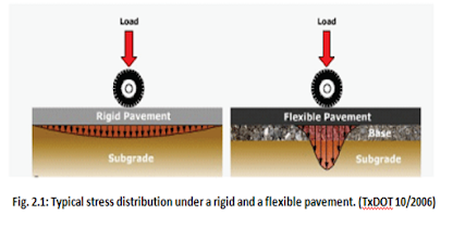
Stresses in Rigid Pavement :-
•
IN IRC 58:2015, Typical cross sections of two
pavements are shown.
–
(a) Debonding Layer of Polythene Sheet Over DLC

–
(b) Debonding Layer of 30 to 40 mm BC1 Over Cement
Treated Subbase Layer

• Typical type of pavements
– CRPC:- Complete reinforcement in longitudinal direction

•
Does not require any transverse contraction joint
• Transverse cracks are acceptable in slab at 0.5 to 1.5m interval held together By designed reinforcement 0.6 to 0.7 % of area for holding cracked concrete together
•
More effective life than JPCP, JRCP
•
Good candidate for asphalt surfacing due to tight crack
width and minimal vertical movements between adjacent vertical joints
• Design life 30-40 years
• Cab be resurfaced later
• Costlier than JPCP due to steel
• The reinforcement in the rigid pavement is designed to prevent opening or widening of cracks, it has no role in contribution of flexural resistance.

– JPCP:- Jointed Plain Concrete Pavement, No steel (apart from dowel and tie bar) – Most commonly used in India

• Uses contraction joints to control cracking
• Typical Slab size 3.5 to 3.75m X 4.5m
• Has longitudinal and Transverse joints at Every 3.5 to 4.5 m interval
• Has dowel bars across Transverse joints
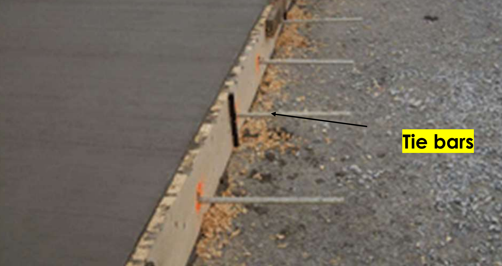
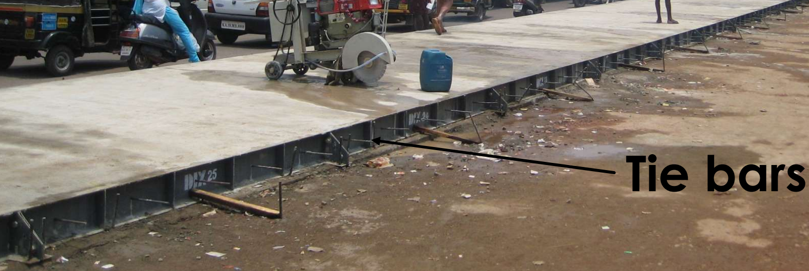
• Has Tie bars across Longitudinal joints

– JRCP:-Jointed reinforced concrete pavement, Nominal Steel

• Transverse joint spacing longer than that for JPCP
• Typical Slab size 3.5 to 3.75m X 9 to 15 m
• Has dowel bars across Transverse joints
• Has Tie bars across Longitudinal joints
• Additional steel mesh
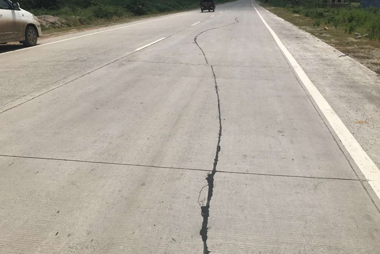
• Crack observed at Midpanel-held by steel

JRCP
Design of Slab Thickness for Pavement
(with and without doweled transverse joints. Beta value will be 0.66 for doweled joint and 0.90 for without dowels case)
Typical Layers of the Rigid Pavement
PQC (Pavement Quality Concrete) Slab – M40 grade and above generally 200 to 350 mm thickness
Polythene Membrane/Sheet – Separation sheet (200 micron)
Dry Lean Concrete Base (DLC) – generally M 10 with thickness 100 to 150 mm thickness as upper Subbase
Granular Subbase as drainage layer as lower subbase (permeability 300 m per day)
Soil subgrade minimum 8 % CBR
Subgrade
Materials:
Requirements of materials:

Construction procedure:
Subbase - GRANULAR SUB-BASE OR DRAINAGE LAYER:
Materials:
Requirements of materials:
| IS Sieves | I | II | III | IV | V | VI |
| 75 mm | 100 |
- | - | - | 100 | - |
| 53 mm | 80-100 | 100 | 100 | 100 | 80-100 | 100 |
| 26.5 mm | 55-90 | 70-100 | 55-75 | 50-80 | 55-90 | 75-100 |
| 9.5 mm | 35-65 | 50-80 | - | - | 35-65 | 55-75 |
| 4.75 mm | 25-55 | 40-65 | 10-30 | 15-35 | 25-50 | 30-55 |
| 2.36 mm | 20-40 | 30-50 | - | - | 10-20 | 10-25 |
| 0.85 mm | - | - | - | - | 2-10 | - |
| 0.425 mm | 10-15 | 10-15 | - | - | 0-5 | 0-8 |
| 0.075 mm | <5 | <5 | <5 | <5 | - | 0-3 |
Construction procedure:
Quality control tests:
Base course: ( Dry lean concrete):
Requirements of material:
| IS Sieves | % by weight passing the seive |
| 31.5 mm | - |
| 26.5 mm | 100 |
| 19 mm | 75-95 |
| 9.5 mm | 50-70 |
| 4.755 mm | 30-55 |
| 2.36 mm | 17-42 |
| 600 micon | 8-22 |
| 300 micon | 7-17 |
| 150 micon | 2-12 |
| 75 micon | 0-10 |
Construction procedure:
Batching and mixing:
Transporting :
Placing:
Compaction:
Joints:
Curing:
Quality control test:
PQC- PAVEMENT QUALITY CONCRETE REQUIREMENTS

Requirements of material:
| IS Sieves | % by weight passing the seive |
| 31.5 mm | 100 |
| 26.5 mm | 85-95 |
| 19 mm | 68-88 |
| 9.5 mm | 45-65 |
| 4.755 mm | 30-55 |
| 600 micon | 6-30 |
| 150 micon | 5-15 |
| 75 micon | 0-5 |
Construction procedure:
Batching and mixing:
Transporting:
Compaction:
Finishing:
Texture:
Curing:
Quality control tests:
Joints in Rigid Pavement – Transverse/ Contraction Joint

Joints in Rigid Pavement – Longitudinal Joint


Construction Joint


Sealants
1) Hot Poured Rubberized Bitumen Sealant

Contraction Joint

Longitudinal joint

Expansion joint
Note :- There is no need to provide Expansion joints at regular intervals but they are
essential where cement concrete pavement is designed to abut with structures like bridges.
It may sometime be necessary to provide more number of expansion joints in succession
in such locations to release the pressure. Expansion joints against culverts, underpasses
etc. having RCC box structure should normally be avoided by taking the PQC over the
deck of such structures. To deal with the lack of compaction in the vicinity of structures and
subsequent settlement, RCC approach slabs must be provided on both sides abutting with
DLC layer. Wherever, PQC is taken over the deck of structures, underpasses etc., saw cut
transverse construction joints must be provided just above the deck and approach slabs on
both sides to avoid full depth transverse cracks in PQC.
2) Cold Poly-Sulphide Sealant
3) Cold Silicon Sealant


Load transfer across Joints

Dowel Bars


Tie Bars
Separation membrane/Polythene Sheet

Design Of Rigid Pavement as per IRC:58
Carriageway
Shoulders :- Tied concrete shoulders ? (yes/no)
Transverse joint spacing (m)
Spacing of Contraction Joints, (Lc)
Case 1) When reinforcement is not provided
$${L_c}={{(2 \times 10^4){S_c}}\over {w.f}}$$
Where,
Lc = Spacing of Contraction joint (m)
Sc = Allowable stress in tension in cement concrete.
f = Coefficient of friction ~ 1.5
W = Unit weight of cement concrete (Kg/cm3)
Lane width (m)
Transverse Joints have dowel bars? (yes/no)
2) Design Traffic Estimation
Design Period (years)
Total Two-way Commercial Traffic (cvpd) in the year of completion of construction
Av. Annual rate of growth of commercial traffic (expressed as decimal)
Cumulative No of Commercial vehicles during design period
(two-way), A
Average No of axles per commercial vehicle, B
Cumulative No of Commercial Axles during design period (two-way),
C = A*B
Proportion of traffic in predominant direction (For 2-lane 2-way
highways use a value of 1.0), D
Lateral Placement factor (0.25 for 2-lane 2-way. For multilane
highways the value is 0.25 X C), E
Factor for selection of traffic for BUC analysis (for six-hour
period during day), F
• Bottom Up Cracking (BUC)
– 10 am to 4 PM


Factor for selection of traffic for TDC analysis (for six-hour period during day), G
• Top Down Cracking (TDC)
– 0 am to 6 am


Design axle repetitions for BUC analysis (for 6 hour day time
traffic), H = B*E*F
Proportion of vehicles with spacing between front and the first
rear axle less than the spacing of transverse joints, I 0.55
Design axle repetitions for TDC analysis (for 6-hour night time
traffic), J = B*E*G*I
Proportion of Front single (steering) Axles, K1
Proportion of Rear single Axles,K2
Proportion of tandem Axles, K3
Proportion of Tridem Axles, K4 = (1-K1-K2-K3)
Westergards and Bradbury equation for curling stresses
$$\sigma = {{C.E.{\alpha}.Δt}\over 2}$$
C is the correction factor depending in L\l ratio
$$C={\left[{{C_x}+{\mu}{C_y}}\over {1-{\mu}^2}\right]}$$
Cx = Coefficient based on (Lx/l) in desired (X) direction
Cy = Coefficient based on (Ly/l) in right angle to X direction
μ = Poisson's ratio 〜0.15
|
Lx/l or Ly/l |
Cx or Cy |
|
4 |
0.6 |
|
8 |
1.1 |
|
12 |
1.02 |
Lx & Ly are the dimensions of the slab considering x & y direction along the length & width of slab
Warping stress at Edge region (σe) will be maximum of
$$\sigma_e = {{E.{\alpha}.Δt}\over 2}{\,}{C_x}$$
or
$$\sigma_e = {{E.{\alpha}.Δt}\over 2}{\,}{C_y}$$
Warping stress at Corner region (σc)
$$C={{E \alpha T}\over {3({1- \mu})}}{\sqrt{a\over l}}$$
Westergards Stress equation
$${S_i} = {{{0.316 P}\over {h^2}}\left[4.{log_{10}}{\left({l\over b}\right)}+1.069\right]}$$
Stress at Edge loading
$${S_e} = {{{0.572 P}\over {h^2}}\left[4.{log_{10}}{\left({l\over b}\right)}+0.359\right]}$$
Stress at Corner loading
$${S_c} = {{{3 P}\over {h^2}}\left[{1-\left({{a\sqrt 2}\over l}\right)^{0.6}}\right]}$$
Where,
h = slab thickness (cm)
a =radius of contact area (cm)
P = wheel load (Kg)
b = radius at resisting section (cm)
radius at resisting section (b) when a < 1.724 h
$$b=\sqrt{1.6.a^2 + h^2}-0.675h$$
radius at resisting section (b) when a >1.724 h
b = a
Combination of Stresses
1) Critical Combination during Summer
i) Stress for edge/interior regions at bottom = Load stress + warping stress of day time - Frictional stress
ii) Stress for corner region at top = Load stress + warping stress at night
2) Critical Combination during Winter
i) Stress for edge/interior regions at bottom = Load stress + warping stress of day time + Frictional stress
ii) Stress for corner region at top = Load stress + warping stress at night
3) Pavement Structural Details
Modulus of subgrade reaction of subgrade (k), MPa/m
$$k = {P\over \delta}$$
P = pressure required for δ deflection (Kg/cm2)
δ = deflection (cm)
Thickness of Granular Subbase, mm
Thickness of Dry Lean Concrete subbase, mm
Effective modulus of subgrade reaction of foundation, MPa/m
Unit
weight of Concrete, kN/m3
28-day Flexural strength of cement concrete, MPa
Max. day-time Temperature Differential in slab, 0C (for
bottom-up cracking)
Night-time Temperature Differential in slab, 0C (for
top-down cracking) = day-time diff/2 + 5
Trial Thickness of Concrete Slab, m
Load Transfer Efficiency Factor for TDC analysis,
Beta = 0.66 for dowel Joints,
Beta = 0.90 for joints without dowels
Elastic Modulus of Concrete, Ec (MPa)
Poisson's Ratio of Concrete, μ
Radius of relative stiffness, l
$$l={{\left[{{Eh^3}\over {12k{(1-{\mu}^2)}}}\right]}^{1\over 4}}$$
l =radius of relative stiffness , cm
E = modulus of elasticity of cement concrete (kg/cm2)
μ = Poisson's Ratio of Concrete = 0.15
h = slab thickness (cm)
k = Modulus of subgrade reaction of subgrade (kg/cm3)
4) Design Axle Load Repetitions for Fatigue Analysis
Front single (steering) Axles = H * K1
Rear single Axles = H * K2
Tandem Axles = H * K3
Tridem Axles = H * K4
b) For Top-Down Cracking Analysis
Front single (steering) Axles = J * K1
Rear single Axles = J * K2
Tandem Axles = J * K3
Tridem Axles = J * K4
The subgrade is usually considered as a Winkler foundation, also known as dense liquid foundation. In Winkler model, it is assumed that the foundation is made up of springs supporting the concrete slab. The strength of subgrade is expressed in terms of modulus of subgrade reaction, k, which is defined as the pressure per unit deflection of the foundation as determined by plate load tests. The k-value is determined from the pressure sustained at a deflection of 1.25 mm.
As k-value is influenced by test plate diameter, the standard test is to be carried out with a 750 mm diameter plate. IS:9214, “Method of Determination of Modulus of Subgrade Reaction of Soil in the Field” may be referred to for guidance in this regard.
A frequency of one test per km per lane is recommended for assessment of k-value. If the foundation changes with respect to subgrade soil, type of subbase or the nature of formation (i.e. cut or fill) then additional tests may be conducted. 5.7.3.2 Though 750 mm is the standard plate diameter, smaller diameter plate can be used in case of homogeneous foundation from practical consideration and the test values obtained with plates of smaller diameter may be converted to the standard 750 mm plate value using equation.
k750 = kᵩ (1.21 f +0.078)
Φ = plate diameter, metre
kΦ = modulus of subgrade
reaction (MPa/m) with plate diameter Φ metre
k750 = modulus of
subgrade reaction (MPa/m) with plate diameter of 750 mm (k)
Axle Load Spectrum Data
| Rear Single Axle | Rear Tandem Axle | Rear Tridem Axle | ||||||
| Load Group (KN) | Mid-Point of Load Group (KN) | Frequency (%) | Load Group (KN) | Mid-Point of Load Group (KN) | Frequency (%) | Load Group (KN) | Mid-Point of Load Group (KN) | Frequency (%) |
| Rear Single Axle | Rear Tandem Axle | Rear Tridem Axle | ||||||||||||
| Expected Repetitions (ni) | Flexural stress (MPa) | Stress Ratio (SR) | Allowable Repetiotions (Ni) | Fatigue Damage (ni/Ni) | Expected Repetitions (ni) | Flexural stress (MPa) | Stress Ratio (SR) | Allowable Repetiotions (Ni) | Fatigue Damage (ni/Ni) | Expected Repetitions (ni) | Flexural stress (MPa) | Stress Ratio (SR) | Allowable Repetiotions (Ni) | Fatigue Damage (ni/Ni) |
| Bottom-up Cracking Fatigue analysis for day time (6 Hour) and positive temperature differential | |||||||||
| Rear Single Axle | Rear Tandem Axle | ||||||||
| Expected Repetitions (ni) | Flexural stress (MPa) | Stress Ratio (SR) | Allowable Repetiotions (Ni) | Fatigue Damage (ni/Ni) | Expected Repetitions (ni) | Flexural stress (MPa) | Stress Ratio (SR) | Allowable Repetiotions (Ni) | Fatigue Damage (ni/Ni) |
Frequency (%) in that Load Group * Number of that type of Axles (Applicable for BUC & TDC)
Flexural stress MPa
Single axle – Pavement with tied concrete shoulders
(a) k ≤ 80 MPa/m
S = 0.008 – 6.12 (γh2 /kl2 ) + 2.36 Ph/(kl4 ) + 0.0266 ΔT
(b) k > 80 MPa/m, k ≤ 150 MPa/m
S = 0.08 – 9.69 (γh2 /kl2 ) + 2.09 Ph/(kl4
) + 0.0409 ΔT
(c) k > 150 MPa/m
S = 0.042 + 3.26 (γh2 /kl2 ) + 1.62 Ph/(kl4 ) + 0.0522 ΔT
Single axle – Pavement without concrete shoulders
(a) k ≤ 80 MPa/m
S = - 0.149 - 2.60 (γh2 /kl2 ) + 3.13 Ph/(kl4
) + 0.0297 ΔT
(b) k > 80 MPa/m, k ≤ 150 MPa/m
S = - 0.119 - 2.99 (γh2 /kl2 ) + 2.78 Ph/(kl4
) + 0.0456 ΔT
(c) k > 150 MPa/m
S
= - 0.238 + 7.02 (γh2 /kl2 ) + 2.41 Ph/(kl4 )
+ 0.0585 ΔT
Tandem axle – Pavement with tied concrete shoulders
(a) k ≤ 80 MPa/m
S = - 0.188 + 0.93 (γh2 /kl2 ) + 1.025 Ph/(kl4 ) + 0.0207 ΔT
(b) k > 80 MPa/m, k ≤ 150 MPa/m
S = - 0.174 + 1.21 (γh2 /kl2 ) + 0.87 Ph/(kl4 ) + 0.0364 ΔT
(c) k > 150 MPa/m
S
= - 0.210 + 3.88 (γh2 /kl2 ) + 0.73 Ph/(kl4 )
+ 0.0506 ΔT
Tandem axle – Pavement without concrete shoulders
(a) k ≤ 80 MPa/m
S = - 0.223 + 2.73 (γh2 /kl2 ) + 1.335 Ph/(kl4 ) + 0.0229 ΔT
(b) k > 80 MPa/m, k ≤ 150 MPa/m
S = - 0.276 + 5.78 (γh2 /kl2 ) + 1.14 Ph/(kl4
) + 0.0404 ΔT
(c) k > 150 MPa/m
S
= - 0.3 + 9.88 (γh2 /kl2 ) + 0.965 Ph/(kl4 ) +
0.0543 ΔT
In Excel sheet formula for Rear Single Axle can be given as below in Excel attached in link
=IF(B$8="yes",IF(E$9<=80,0.008-(6.12*E$10*E$14*E$14/(E$9*E$18*E$18))+(2.36*H9*E$14/(E$9*E$18^4))+0.0266*E$12,IF(AND(E$9>80,E$9<=150),0.08-(9.69*E$10*E$14*E$14/(E$9*E$18*E$18))+(2.09*H9*E$14/(E$9*E$18^4))+0.0409*E$12,0.042+(3.26*E$10*E$14*E$14/(E$9*E$18*E$18))+(1.62*H9*E$14/(E$9*E$18^4))+0.0522*E$12)),IF(E$9<=80,-0.149-(2.6*E$10*E$14*E$14/(E$9*E$18*E$18))+(3.13*H9*E$14/(E$9*E$18^4))+0.0297*E$12,IF(AND(E$9>80,E$9<=150),-0.119-(2.99*E$10*E$14*E$14/(E$9*E$18*E$18))+(2.78*H9*E$14/(E$9*E$18^4))+0.0456*E$12,-0.238+(7.02*E$10*E$14*E$14/(E$9*E$18*E$18))+(2.41*H9*E$14/(E$9*E$18^4))+0.0585*E$12)))
Similarly it can be written for other cases also.
Stress Ratio
Flexural stress/(28-day Flexural strength of cement concrete * 1.1)
Relation between fatigue life (N) and stress ratio (SR)
1) N = Unlimited for SR < 0.45
2) When 0.45 < SR < 0.55 $$N={\left[4.2537\over {SR-0.4235}\right]^{3.268}}$$
Bottom-up Cracking
Pavement
with tied concrete shoulders for single rear axle
Pavement
without concrete shoulders for single rear axle
Pavement
with tied concrete shoulders for tandem rear axle
Pavement without concrete shoulders for tandem rear axle
Fatigue Damage Analysis
| Top-Down Cracking Fatigue analysis for Night-time (6 Hour) and Negative Temperature Differential | ||||||||||||||
| Rear Single Axle | ||||||||||||||
| Expected Repetitions (ni) | Flexural stress (MPa) | Stress Ratio (SR) | Allowable Repetiotions (Ni) | Fatigue Damage (ni/Ni) | ||||||||||
| Rear Tandem Axle(Stress computed for 50% of axle load) | ||||||||||||||
| Expected Repetitions (ni) | Flexural stress (MPa) | Stress Ratio (SR) | Allowable Repetiotions (Ni) | Fatigue Damage (ni/Ni) | ||||||||||
| Rear Tridem Axle(Stress computed for 33% of axle load) | ||||||||||||||
| Expected Repetitions (ni) | Flexural stress (MPa) | Stress Ratio (SR) | Allowable Repetiotions (Ni) | Fatigue Damage (ni/Ni) | ||||||||||
Top-down Cracking
Pavements with and without dowel bars having front steering axle with single tyres and the first axle of the rear axle unit (single/tandem/tridem) placed on the same panel.
Fcr =0.7*√Fck
Total Bottom-up Fatigue Damage due to single and tandem axle loads = X
Total Top-Down Fatigue Damage = Y
Sum of CFD for BUC & TDC= X +Y
Condition --> SUM OF CFD FOR BUC AND TDC< 1
if above condition satisfies then the pavement is safe from large scale cracking.
Design for Bonded Pavement Option
Subgrade CBR (%)=
Granular Subabse Thickness (mm) =
Effective k-value from Tables 2 and 3 (MPa/m) =
| Relationship between K-value and CBR value for Homogeneous soil subgrade | ||||||||||
| Soaked CBR | 2 | 3 | 4 | 5 | 7 | 10 | 15 | 20 | 50 | 100 |
| K-value | 21 | 28 | 35 | 42 | 48 | 55 | 62 | 69 | 140 | 220 |
Table 2 of IRC:58-2015
For k of K' MPa/m and for
| K-Value of Subgrade (MPa/m) | Effective k (MPa/m) of Untreated Granular Subbase of Thickness (mm) | Effective k (MPa/m) of Cement Treated Subbase of Thickness (mm) | ||||
| 150 | 225 | 300 | 100 | 150 | 200 | |
| 28 | 39 | 44 | 53 | 76 | 108 | 141 |
| 56 | 63 | 75 | 88 | 127 | 173 | 225 |
| 84 | 92 | 102 | 119 | |||
Table 3 of IRC:58-2015
|
K-Value for Dry Lean Concrete subbase |
||||||
|
K- Value of Subgrade(Mpa/m) |
21 |
28 |
42 |
48 |
55 |
62 |
|
Effective k for 100 mm DLC, (Mpa/m) |
56 |
97 |
166 |
208 |
278 |
300 |
|
Effective k for 100 mm DLC, (Mpa/m) |
97 |
138 |
208 |
277 |
300 |
300 |
Table 4 of IRC:58-2015
For concrete pavements laid over a bituminous subbase, the k-value can be adopted from IRC:SP:76. k-values for different combinations of DLC subbase (with DLC having minimum 7-day compressive strength of 7 MPa) thicknesses laid over granular subbase consisting of separation and drainage layers can be adopted from Table 4.
Doweled Joint and Tied Concrete Shoulders, Slab Thickness (m) =
Trial Slab thickness (m) over DLC, h1
Provide DLC thickness (m), h2
Elastic Modulus of Pavement Concrete (MPa), E1
Elastic Modulus of DLC (MPa), E2
Poisson's Ratio of Paving Concrete, m1
Poisson's Ratio of DLC, m2
Depth to Neutral axis, m

Flex Stiffness of design Slab
Flexural stiffness of a slab of thickness, h, is given as
Flex Stiffness of Partial Slab Provided
Flex Stiffness of DLC
Total Flexural Stiffness Provided = Z1
which is more than the Flexural Stiffness of the Design Slab
= Z2
Hence, Provide a Slab of thickness (m)
Slab thickness (h1) over DLC layer may be obtained by iteratively
changing h1 and matching the design stiffness with the combined stiffness
provided.
Maximum
Temperature Differentials for Concrete slabs
|
Zone |
Stages/Regions |
||||
|
150 mm |
200 mm |
250 mm |
300 to 400 mm |
||
|
I |
Hilly regions of Uttaranchal, West Bengal, Jammu
& Kashmir, Himachal Pradesh and Arunachal Pradesh |
12.5 |
13.1 |
14.3 |
15.8 |
|
II |
Punjab, U.P., Uttaranchal, Gujarat, Rajasthan,
Haryana and North M.P, excluding hilly regions. |
12.5 |
13.1 |
14.3 |
15.8 |
|
III |
Bihar, Jharkhand, West Bengal, Assam and Eastern
Orissa, excluding hilly regions and costal areas |
15.6 |
16.4 |
16.6 |
16.8 |
|
IV |
Maharashtra, Karnataka, South M.P., Chhattisgarh,
Andhra Pradesh, Western Orissa and North Tamil Nadu, excluding hilly regions
and costal areas. |
17.3 |
19 |
20.3 |
21 |
|
V |
Kerala and South Tamil Nadu, excluding hilly regions
and coastal areas |
15 |
16.4 |
17.6 |
18.1 |
|
VI |
Coastal areas bounded by hills |
14.6 |
15.8 |
16.2 |
17 |
|
VII |
Coastal areas unbounded by hills |
15.5 |
17 |
19 |
19.2 |
Design of Dowel Bars
Design Parameters
Design wheel load = 98 percentile axle load is X tonnes, the wheel
load therefor is X/2000 kg (dual wheel load)
Percentage of load transfer = a%
Slab Thickness h = --- mm
Joint Width, z = --- mm
Assumed Dia of dowel bar in cm = ---- mm
Permissible bearing stress in concrete is calculated as shown in equation below
Fb = -----
Assumed spacing between dowel bars = ----- mm
First dowel is placed at a distance = ----- mm from the pavement edge
Assumed length of dowel bar = ----- mm
Dowel bars upto a distance of 1.0 X radius of relative stiffness,
from the point of load application are effective in load transfer.
No. Of Dowel bars participating in load transfer when wheel load
is just over the Dowel bar close to the edge of the slab
= ---- Dowels
to b zero, the total load transferred by dowel bar system = ----- Pt
load transferred by outer dowel bar Pt = ------- Kg
Check for Bearing stress
Maximum bearing stress (Fbmax) between the concrete and dowel bar is obtained from equation
Moment of Inertia of Dowel = I
Relative stiffness of the bar embedded in concrete, mm-1 (β)
Relative stiffness of Dowel bar embedded in concrete = (β)
Bearing stress in Dowel bar = Fbmax < Fb then Safe
Design of Tie bars
Coefficient of friction, f = -----
Density of Concrete = 24000 N/mm3
Allowable tensile stress in Plain Bars = -----
Kg/cm2 (As per IRC:21 - 2000)
Allowable tensile stress in Deformed Bars = ------
Kg/cm2 (As per IRC:21 - 2000)
Allowable Bond stress for Plain tie bars = ------
Allowable Bond stress for Deformed tie bars = -----
Assumed dia of tie bar in mm -----
Spacing and Length of plain Bar
Area of steel Bar per meter width of joint to resist
the frictional force at slab bottom (As) = =
------ cm2/m
Assuming the Diameter of 12
mm, the cross sectional area A =
----- cm2
Perimeter of tie Bars (P) = P = ------ cm
Spacing of tie Bars = =
------ cm
Provide at a Spacing of
-------cm C/C
Length of tie Bar = =
------- cm
length to be increased for loss of Bond(cm) = ----- cm
Tolerence in Placement (cm) = ----- cm
Therefor length is =
------ cm Say
------- cm
Spacing and Length of Deformed Bar
Area of steel Bar per meter width of joint to resist
the frictional force at slab bottom (As) = =
--------- cm2/m
Assuming the Diameter of ----- mm, the cross sectional area A = ------ cm2
Perimeter of tie Bars (P) = P = ------ cm
Spacing of tie Bars = ------- cm
Provide at a Spacing of ----- cm
C/C
Length of tie Bar = -------- cm
length to be increased for loss of Bond(cm) = ------- cm
Tolerance in Placement (cm) = ------- cm
Therefor length is = ------- cm Say ------- cm
Design for rigid pavements having traffic less than 450 CVPD as per IRC:SP:62-2014
Input values in Red only


0 Comments
If you have any doubts, suggestions , corrections etc. let me know